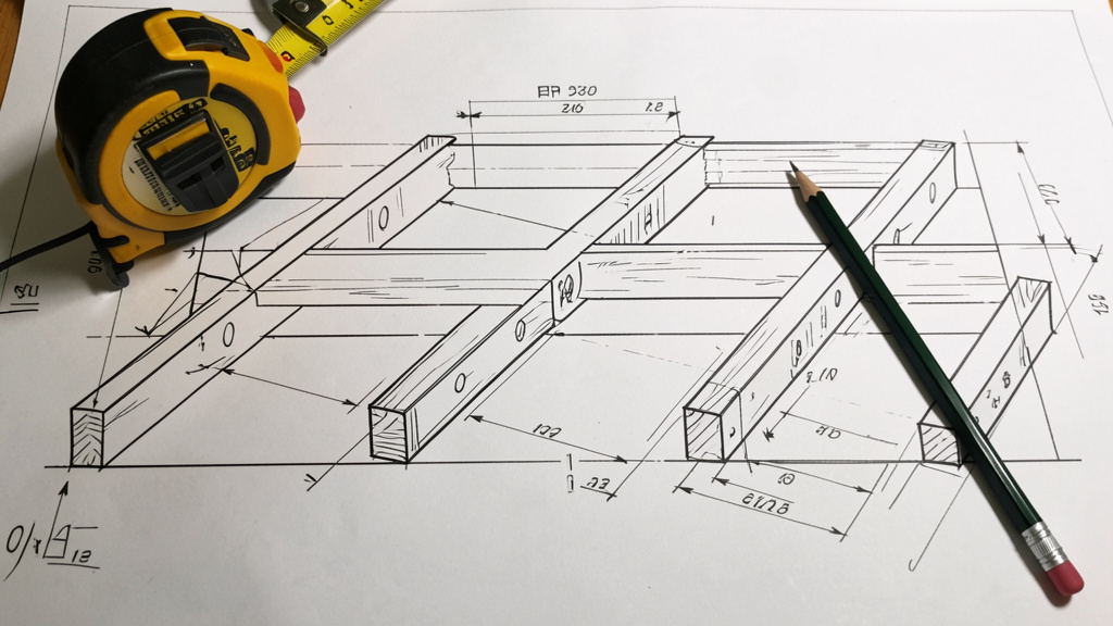
Stop Guessing—Learn How to Confidently Calculate, Select, and Install Floor Joists for Typical Residential Loads While Minimizing Risks of Sagging, Bouncing, or Failure
Choosing appropriate floor joist dimensions and spans requires understanding the interplay of structural physics, material properties, environmental conditions, and building code requirements. This guide synthesizes International Residential Code (IRC) standards, American Wood Council (AWC) resources, and field-tested installation practices into an actionable framework. Whether framing a garden shed, renovating an older home’s subfloor, or planning a second-story addition, you’ll gain clarity on making informed structural decisions—and recognizing precisely when professional engineering input becomes essential.
Introduction
Beneath every quiet step and stable surface lies an unseen structural network: your floor joists. These horizontal members form the skeleton of your floor system, transferring loads from living spaces down through walls, beams, and ultimately to the foundation. Under-sizing joists—by underestimating loads, misapplying span tables, or overlooking moisture exposure—can lead to excessive deflection, cracked finishes, or compromised structural integrity. Conversely, over-engineering with unnecessarily large joists wastes materials, reduces usable space, complicates mechanical installations, and increases project costs without meaningful safety gains.
This resource addresses a critical gap in fragmented online information: isolated span charts without context, omitted nuances about wood grading, or failure to address how modern design choices (like open-concept layouts) fundamentally alter joist requirements. Grounded in the currently adopted International Residential Code (IRC), AWC publications, and documented field performance across diverse climate zones, we break down joist selection into a logical, sequential methodology. You’ll move beyond memorizing numbers toward understanding why specific dimensions suit specific scenarios. We emphasize safety margins, code compliance pathways, and practical installation techniques that prevent common pitfalls—from inadequate bearing surfaces to improperly placed penetrations. This is applied knowledge designed to support safe, resilient construction. Before proceeding, remember this foundational principle: floor joists function as part of an integrated system. Subfloor sheathing, blocking, beam support, and wall framing collectively influence performance. Overlooking these connections is where well-intentioned projects often encounter difficulties.
The Load-Bearing Framework: A 4-Step System for Confident Joist Sizing
True confidence comes from adopting a systematic approach that accounts for every variable influencing joist performance. We call this the Load-Bearing Framework—a sequential process transforming complexity into manageable decisions. This framework builds intuitive understanding of how forces travel through your structure. Follow these steps in order; skipping ahead risks critical oversights.
Step 1: Quantify Every Load Acting on Your Floor System
Before selecting materials, calculate the total weight your joists must support. Loads fall into two essential categories defined by engineering standards:
Dead Loads: The Permanent Weight
These are static weights inherent to the structure:
– Subflooring (¾” plywood: ~2.0 psf; ¾” OSB: ~2.2 psf)
– Finished flooring (hardwood: 3–4 psf; tile with mortar: 5–7 psf; carpet: 1–2 psf)
– Ceiling materials below (½” drywall: 2.5 psf)
– Insulation in cavities (fiberglass: ~0.3 psf)
– Mechanical systems (wiring, pipes: ~1.0 psf)
Example Calculation:
A second-floor bedroom with ¾” OSB subfloor (2.2 psf), hardwood (3.5 psf), drywall ceiling (2.5 psf), and insulation (0.5 psf) totals 8.7 psf. Industry practice typically rounds to 10 psf for conservative design—a prudent buffer for unforeseen additions like thicker underlayment.
Live Loads: The Variable, Occupant-Driven Weight
These are temporary forces defined by IRC Table R301.5:
– Bedrooms, attics (with storage): 30 psf
– Living rooms, kitchens, hallways: 40 psf
– Decks: 40 psf (plus snow load considerations)
– Garages (vehicle storage): 50 psf
– Heavy storage/workshops: 75–100+ psf
Critical Context: “psf” means pounds per square foot. A 10′ x 12′ living room (120 sq ft) designed for 40 psf live load must support 4,800 pounds of variable weight alone. Add dead load (10 psf = 1,200 lbs), and total load reaches 6,000 pounds. This illustrates why precise load calculation matters far more than visual estimation.
Special Load Considerations:
– Concentrated Loads: Grand pianos, large aquariums, or heavy safes create localized stress exceeding uniform load assumptions. These typically require targeted reinforcement—doubling joists or adding beams beneath the point load. Never assume standard spacing accommodates concentrated weights.
– Snow Loads on Decks: While deck floors use 40 psf live load, snow accumulation adds significant weight. Regional snow load maps (referenced in local codes) dictate additional requirements. Total deck loading can substantially exceed interior floor demands.
– Deflection Limits (The “Bounce” Factor): Codes specify maximum allowable deflection under live load: L/360 for floors supporting plaster ceilings, L/240 for standard drywall ceilings, and L/180 for unfinished spaces. “L” is the span in inches. For a 14-foot (168-inch) span, L/360 permits only 0.47 inches of sag under full live load. Exceeding this causes perceptible bounce and finish damage—even if structural failure hasn’t occurred. Span tables often list two values: one for bending strength (safety) and one for deflection (serviceability). Deflection frequently governs joist selection in modern homes, especially with open layouts and lightweight finishes.
The Fundamental Principle: Total Load = Dead Load + Live Load + Special Loads. Underestimating any component risks performance issues; overestimating unnecessarily increases cost and complexity. Precision here anchors every subsequent decision.
Step 2: Decode Material Properties—Species, Grade, and Engineered Alternatives
Not all dimensional lumber performs identically. A Southern Pine 2×10 carries significantly more load than a Spruce-Pine-Fir (SPF) 2×10 of identical dimensions. Material selection is as critical as dimensional sizing.
Solid Sawn Lumber: Understanding Species and Grade Stamps
Grade stamps (e.g., “S-P-F 2400Fb 1.7E”) provide certified structural properties:
– Species Group: Key U.S. groups per AWC:
– Southern Pine (SP): Highest bending strength (Fb) and stiffness (E). Common in Southeast U.S.
– Douglas Fir-Larch (DF-L): Excellent strength-to-weight ratio. Widely used in Western states.
– Hem-Fir (HF): Moderate strength. Common in Pacific Northwest.
– Spruce-Pine-Fir (SPF): Most available nationwide. Lower strength values than SP or DF-L—requiring larger dimensions or closer spacing for equivalent performance. Never substitute SPF for SP in a design without recalculating spans.
– Grade: Reflects allowable defects:
– No.1 & Better: Highest structural grade. Minimal defects.
– No.2: Most common for hidden framing. Cost-effective with reliable strength.
– Stud Grade: Never use for floor joists. Optimized for vertical compression (walls), not horizontal bending.
– Design Values (Fb, E, Fv):
– Fb (Bending Strength): Higher = greater resistance to breaking. SP No.2: ~1,400 psi; SPF No.2: ~1,100 psi.
– E (Modulus of Elasticity): Stiffness. Higher = less deflection. SP: ~1.6 million psi; SPF: ~1.4 million psi. This difference explains why SP 2x10s may span farther than SPF equivalents.
Practical Insight:
For a 15-foot span living room (40 psf live load), SPF No.2 2x10s may max out near 14′ at 16″ o.c., while Southern Pine No.2 2x10s may reach 15′ 5″. Verifying the actual grade stamp on delivered lumber is essential—marketing terms like “premium” don’t guarantee structural grade.
Engineered Wood Products: When to Choose I-Joists, LVL, or TJIs
Engineered options address specific challenges solid lumber cannot:
– Wood I-Joists: Top/bottom flanges (LVL or solid sawn) with an OSB web. Advantages:
– Predictable Performance: Minimal shrinkage, warping, or twisting.
– Longer Spans: Efficient depth-to-strength ratio. An 11¾” deep I-joist often spans farther than a 2×12 solid lumber joist.
– Utility-Friendly: Large, uniform web openings simplify running utilities (follow manufacturer hole charts precisely).
– Critical Note: Vulnerable to impact damage during construction. Never notch flanges or webs. Requires manufacturer-specific hangers and bearing details. Always use the manufacturer’s span tables—not generic IRC tables.
– Laminated Veneer Lumber (LVL): Thin veneers bonded under heat/pressure. Primarily used for headers, beams, or specialty long-span applications. Typically more expensive than I-joists for standard floor framing.
– Trus Joists (TJIs): Proprietary I-joist systems with optimized designs. Performance aligns with standard I-joists but requires adherence to specific manufacturer guidelines.
When Engineered Joists Are Advantageous:
– Open-concept homes requiring clear spans beyond 16 feet
– Renovations where minimizing floor depth preserves ceiling height
– Projects prioritizing consistent performance and reduced long-term movement
– Areas with strict deflection requirements (e.g., L/480 for tile installations)
Budget Consideration:
Engineered joists often carry a higher initial material cost than solid lumber. However, factor in potential labor savings (straightness reduces shimming), reduced callbacks for movement-related issues, and design flexibility. For small sheds or non-critical storage areas, solid SPF may be economical. For primary living spaces where performance and longevity matter, engineered options often deliver better long-term value.
Step 3: Navigate Span Tables with Precision and Context
Span tables are indispensable—but dangerously misleading if used without understanding their embedded assumptions. IRC Chapter 5 tables apply only when all project conditions match the table’s parameters exactly.
Decoding a Standard IRC Span Table Entry
Example for Douglas Fir-Larch, No.2 Grade, 16″ on-center spacing:
| Joist Size | Max Span (ft-in) for 30 psf Live Load | Max Span (ft-in) for 40 psf Live Load |
|————|—————————————-|—————————————-|
| 2×8 | 11′ 1″ | 10′ 0″ |
| 2×10 | 14′ 3″ | 12′ 9″ |
| 2×12 | 17′ 0″ | 15′ 0″ |
What This Means:
– “Max Span” = Center-to-center distance between supports (beams, walls, girders).
– Critical Assumptions Include:
– Dead load ≤ 10 psf
– Deflection limit of L/360
– Continuous spans over 3+ supports (single-span applications reduce allowable length)
– Proper bearing (1.5″ minimum on wood, 3″ on masonry)
– No notching, holes, or modifications
– Standard moisture content (<19% at installation)
– Essential Adjustment Factors:
– Spacing: Switching from 16″ o.c. to 12″ o.c. increases span capacity by 15–20%. Conversely, 24″ o.c. spacing (common with I-joists) reduces solid lumber spans significantly.
– Single-Span Penalty: Joists resting on only two supports require reducing IRC table spans by approximately 15%.
– Wet Service Factor: For lumber exposed to moisture >19% (e.g., unconditioned crawlspaces without vapor barriers), allowable spans are reduced. Consult AWC guidelines for precise multipliers.
– Incising Factor: Pressure-treated lumber for ground contact is often incised, reducing strength. Manufacturer data provides applicable adjustment factors.
Practical Workflow for Using Span Tables:
1. Calculate total load (Step 1).
2. Identify your lumber species/grade (Step 2).
3. Determine required spacing (12″, 16″, or 24″ o.c.—based on subfloor type and deflection needs).
4. Locate the table matching species, grade, spacing, and live load.
5. Apply relevant adjustment factors (single-span? wet service?).
6. Verify deflection: If your room has plaster ceilings or tile flooring, confirm the table’s deflection-limited span (often shorter than the bending-limited span).
7. Apply prudent margin: When calculations yield borderline values (e.g., 14′ 2″), designing for the next lower increment (14′ 0″) provides added assurance.
Why Generic Online Tables Fall Short:
Many websites publish “universal” span charts ignoring species differences. A table claiming “2×10 spans 16 feet” might apply to Southern Pine at 12″ o.c. with 30 psf load—but be unsafe for SPF at 16″ o.c. with 40 psf load. Always trace tables to authoritative sources: IRC, AWC publications, or specific engineered product manufacturer data. When uncertainty exists, consulting the Wood Structural Design Data (WSDD) manual or a qualified professional is prudent.
Step 4: Validate with Real-World Constraints and Installation Physics
Theoretical calculations require validation against jobsite realities. Installation details can make or break structural performance.
Bearing Length: A Critical Detail
Joists must rest fully on solid, level surfaces. IRC requires:
– Minimum 1.5 inches of bearing on wood or metal supports
– Minimum 3 inches of bearing on masonry (concrete, block)
Why it matters: Insufficient bearing concentrates load, potentially crushing wood fibers at support points. Always verify bearing during layout. Use joist hangers rated for your specific joist size and load—never rely solely on toe-nailing. For masonry supports, install a pressure-treated sill plate (minimum 2×4) anchored per code; joists bear on the sill plate, not directly on concrete.
Blocking and Bridging: Controlling Movement
– Solid Blocking: Short lumber pieces fitted tightly between joists. Critical for:
– Preventing joist rotation under load
– Providing edge support for subfloor panels (reducing squeaks)
– Creating fire stops in multi-story construction
– Installation Tip: Install blocking before subfloor goes down. Stagger blocks in alternating bays. Use construction adhesive plus nails for rigid connection.
– Cross Bridging (Metal or Wood): X-shaped braces between joists. Primarily controls vibration in longer spans (>12′). Less effective than solid blocking for edge support but sometimes easier to install after partial subfloor placement. Modern practice often favors continuous blocking for floor systems.
Holes, Notches, and Modifications: Proceed with Caution
Field modifications for utilities are common—but incorrect execution compromises integrity. Follow these guidelines:
– Notching:
– Allowed only in the top 1/6 of joist depth (e.g., max 1.5″ deep on a 2×10)
– Never notch the middle third of the span (highest bending stress zone)
– Never notch the bottom edge (tension zone)—this significantly weakens the joist
– Max notch width = 1/3 joist depth
– Holes (Drilling):
– Location: Centered vertically in the web. Minimum 2″ from top/bottom edges.
– Size: Max hole diameter = 1/3 joist depth (e.g., 3″ max in a 2×10).
– Spacing: Holes must be ≥ 2x hole diameter apart.
– Critical Exception: I-joists require strict adherence to manufacturer hole charts. Never drill outside designated zones.
– Sistering: To repair or strengthen a joist:
– Use lumber matching species and grade where possible
– Extend sister joist ≥ 3 feet beyond the affected area on both sides
– Fasten with structural screws or nails per code requirements
– Construction adhesive between members enhances composite action
Moisture and Environmental Considerations
– Crawlspaces: Install a continuous vapor barrier (6-mil poly, seams overlapped and taped) over soil. Maintain ventilation per local code requirements. Use pressure-treated lumber rated for ground contact where specified.
– Humid Climates: Specify kiln-dried (KD) lumber to minimize post-installation movement. Avoid “green” lumber for floor framing.
– Termite-Prone Areas: In high-risk regions, use pressure-treated lumber or non-cellulose alternatives for framing near soil. Install physical termite barriers per local guidelines.
This framework transforms joist sizing from estimation into a repeatable, reasoned process. By rigorously applying Steps 1–4, you eliminate dangerous assumptions and build with justified confidence. Next, we address complex scenarios where standard tables require thoughtful interpretation.
Beyond the Table: Navigating Complex Scenarios and Hidden Variables
Real-world projects rarely match textbook examples. Historic homes feature irregular layouts. Renovations uncover hidden conditions. Modern designs demand open spaces. This section addresses nuanced challenges generic guides often overlook.
The Renovation Reality: Assessing Existing Joists
You’re remodeling a pre-1950s home. Original 2×8 Douglas Fir joists span 14 feet. IRC tables suggest this may be undersized for modern 40 psf live loads. Replacement isn’t always mandatory—but proceed with careful assessment.
Step-by-Step Existing Joist Evaluation:
1. Identify Species and Grade: Look for original mill stamps (often on top edges). Pre-1950s lumber was frequently old-growth with tighter grain and higher density than modern equivalents. Douglas Fir from this era may perform beyond today’s No.1 grade ratings.
2. Inspect for Damage:
– Rot: Probe with an awl near bearing points, plumbing penetrations, or poorly ventilated areas. Soft, crumbly wood indicates active decay.
– Insect Damage: Look for frass (sawdust-like residue), exit holes, or mud tubes.
– Cracks/Splits: Hairline surface checks are normal. Longitudinal splits exceeding 1/3 joist depth warrant attention.
– Previous Repairs: Document sistered sections, notches, or modifications.
3. Evaluate Current Performance:
– Walk the floor. Does it feel excessively springy? Measure deflection: String a line tight across the span; measure sag at mid-span under concentrated weight. Deflection exceeding L/240 suggests excessive movement.
– Check finishes below: Cracked ceiling drywall or separated crown molding may indicate historical movement.
4. Calculate Actual Load: Older homes often have heavier finishes (plaster walls add significant dead load). However, they may lack modern concentrated loads. Adopt a conservative approach.
5. Strengthening Options (If Needed):
– Sistering: Effective for localized weakness. Match species where feasible.
– Adding a Beam: Install a steel or LVL beam mid-span to effectively halve the joist span. Requires foundation support.
– Specialized Reinforcement: Carbon fiber straps (epoxy-bonded to tension face) offer modern solutions but require specialist installation.
Critical Warning: Never remove existing bracing, blocking, or suspected load-bearing walls during renovation without installing temporary shoring. Floors can fail rapidly. Consult a structural engineer before altering load paths in pre-1980s construction.
Open-Concept Living: Engineering Solutions for Removed Walls
Removing a load-bearing wall to create open space is a common reason engineered solutions become necessary. Standard dimensional lumber rarely spans the resulting 18–24 foot distances safely.
The Beam-and-Joist Strategy:
1. Locate the Load Path: Trace the wall upward. Does it support roof structure or a second-story wall? This determines beam requirements.
2. Temporary Shoring: Install strongbacks (2x10s) under the ceiling on both sides of the wall. Support with adjustable steel posts on solid blocking over floor joists. This step is non-optional.
3. Beam Selection:
– LVL Beams: Most common residential solution. Depths range from 7¼” to 18″. A triple 1.75″ x 11.25″ LVL beam may span 18′ supporting 2×10 joists at 16″ o.c.
– Steel I-Beams: Higher strength-to-depth ratio. Ideal where headroom is critical. Requires fireproofing (½” drywall wrap) per code.
– Flitch Beams: Wood-steel-wood sandwich. Less common today due to LVL availability.
4. Joist Support Details:
– Joists must bear fully on the beam. Use hangers rated for the beam’s load and material.
– For I-joists bearing on LVL, use proprietary top-mount hangers to prevent web crushing.
– Install blocking between joists directly above the beam to distribute loads.
5. Deflection Check: Long-span beams can deflect visibly. Calculate beam deflection separately (L/360 minimum). Excessive beam deflection may cause cracked drywall at wall intersections.
Practical Insight:
While steel beams may have lower material cost than LVL in some regions, factor in installation complexity. Steel requires specialized cutting, welding expertise (if spliced), and fireproofing labor. LVL beams integrate seamlessly with wood framing using standard tools and hardware. For most residential projects, LVL offers the best balance of performance, familiarity, and installer accessibility.
Special Applications: Decks, Attics, and Heavy-Duty Spaces
Deck Joists: Unique Considerations
Decks face moisture exposure, lateral loads, and concentrated point loads.
– Material Choice: Use only lumber rated for “Ground Contact” (UC4B) or “Above Ground” (UC3B) per AWPA standards. Never use interior-grade lumber.
– Spacing: 12″ or 16″ o.c. for standard decking. For diagonal decking (45°), reduce spacing to 12″ o.c. to prevent springiness.
– Overhangs: IRC typically limits cantilevered joist ends to ¼ of the backspan. For a joist spanning 12′ between beams, max overhang = 3′.
– Hot Tub Zone: A 6’x6′ hot tub area requires:
– Joists doubled or tripled under the tub footprint
– Direct beam support beneath (no cantilevers)
– Footings sized for concentrated load
– Engineered plans are strongly recommended for hot tub installations.
Attic Joists: Storage vs. Non-Storage
IRC distinguishes between attic types:
– Non-Storage Attics: Designed for 10 psf live load (access only). Joists may be minimal (e.g., 2×6 SPF at 24″ o.c.).
– Storage Attics: Require 20 psf live load minimum. Existing non-storage attics cannot safely hold stored items without reinforcement. Solutions include:
– Sistering existing joists
– Installing perpendicular strongbacks (2x6s) at mid-span
– Adding intermediate beams with new supports
– Never simply add plywood over undersized joists—that adds dead load without increasing capacity.
Workshops and Garages: Planning for Heavy Equipment
A home workshop storing heavy machinery demands foresight:
– Design for elevated live loads (e.g., 100 psf) in equipment zones
– Use deeper joists (2x12s) at closer spacing (12″ o.c.) or deep-web I-joists
– Install blocking under anticipated equipment foot locations
– Consider localized concrete pads on the subfloor to transfer heavy point loads directly to joists below
– Verify local code requirements for garage floor loading, especially for upper-level garages where snow load may apply
Climate-Specific Considerations: Snow, Seismic Zones, and Humidity
Snow Load Adjustments
Snow load requirements vary significantly by region. IRC maps divide the U.S. into zones with increasing requirements from south to north and elevation.
How it affects floors: If a deck supports a roof (e.g., covered patio), deck joists must carry roof snow load plus deck live load. Total loading can exceed 100 psf in heavy snow zones. This often necessitates deeper joists or closer spacing. Always consult your local building department—they enforce jurisdiction-specific amendments that may exceed IRC minimums.
High-Seismic and High-Wind Regions
In California, Florida, coastal areas, or other designated zones:
– Joist-to-beam connections require hurricane ties or seismic anchors (e.g., “A35” ties)
– Blocking must be installed at all panel edges and at frequent intervals
– Continuous load paths are mandatory: Joists → beams → posts → foundation anchors
– Engineered wood products are often preferred for consistent performance under dynamic loads
– Never rely solely on toenails in these zones. Hardware specifications come from engineered plans or local code amendments.
Humid Climates and Moisture Management
In the Southeast, Gulf Coast, or Pacific Northwest:
– Specify kiln-dried (KD) lumber to minimize post-installation shrinkage (a contributor to squeaks)
– Install continuous vapor barriers in crawlspaces (6-mil poly, seams taped)
– Ensure adequate ventilation per local code (requirements vary with vapor barrier use)
– Use corrosion-resistant fasteners (hot-dipped galvanized or stainless steel) for framing in damp locations
– Consider closed-cell spray foam insulation in joist bays—it acts as an air barrier, but requires careful design to manage condensation risks
Understanding these edge cases prevents critical oversights. However, even perfect calculations require precise installation to perform as intended. Let’s transition to field-proven techniques that ensure your design translates to reliable performance.
Installation Mastery: From Layout to Final Inspection
Theory becomes reality during installation. A correctly sized joist system installed poorly will underperform, develop noise, or fail prematurely. This section details professional techniques established through industry best practices.
Pre-Installation: Layout, Tools, and Material Prep
Precision Layout is Foundational
1. Establish Reference Lines: Snap a chalk line parallel to the supporting wall/beam, offset by the joist depth (e.g., 9¼” for 2x10s). This marks the inside edge of the rim joist.
2. Mark Joist Positions: Starting at one end, mark centers at your specified spacing (12″, 16″, or 24″). Double-check the final interval—accumulated measurement errors often compress the last bay. A story pole (a straight 1×4 marked with spacing intervals) ensures speed and accuracy across long runs.
3. Account for Obstructions: Note locations for stairwells, chimneys, or plumbing stacks early. Plan header placements during layout.
4. Verify Level and Plumb: Use a laser level or long spirit level. An unlevel beam causes uneven loading and visible floor slope. Shim beam supports with galvanized steel shims—not wood scraps that may compress over time.
Essential Tools Checklist
– Measuring: Laser distance measurer, 25′ tape measure, story pole
– Cutting: 12″ compound miter saw, circular saw with sharp framing blade (24-tooth minimum)
– Fastening: Structural screws (3¼”), 16d common nails (3.5″), pneumatic nailer, hammer
– Leveling: 48″ spirit level, laser level
– Safety: Hard hat, safety glasses, hearing protection, knee pads
– Specialty: Joist hanger nails (manufacturer-specified), construction adhesive
Material Handling and Acclimation
– Store lumber on level blocking, covered but ventilated. Never place directly on damp ground.
– Allow wood to acclimate to job site humidity for 48–72 hours before installation to minimize post-installation movement.
– Sort lumber: Set aside significantly twisted, bowed, or cracked pieces for blocking or cutoffs—not primary joists.
Step-by-Step Joist Installation Sequence
1. Install Rim Joists and Headers
– Rim joists (band joists) cap the perimeter. Attach to ledger boards or wall plates with joist hangers or ledger strips.
– Headers span openings (stairs, utilities). Build headers by sandwiching structural panel material (½” plywood/OSB) between two joists. Size headers per span tables—never use single members for header applications.
– Pro Tip: Install rim joists on three sides first. Drop joists into place, then install the fourth rim joist. This creates a stable “basket” for safer working.
2. Position Joists with Correct Orientation
– Crown joists upward. Most lumber has a natural curve (“crown”). Installing crowns upward creates slight upward camber that counteracts deflection under load. Sight down each joist before securing. Mark crowns with chalk if helpful.
– Ensure consistent depth alignment. Misaligned joists cause uneven subfloor surfaces. Use a straightedge across multiple joists to verify alignment.
3. Secure with Code-Compliant Connections
– Joist Hangers:
– Select hangers rated for your joist size, load, and supporting material.
– Fasten hangers to the header before inserting joists where possible.
– Use only the fasteners specified by the hanger manufacturer (typically shorter, thicker joist hanger nails). Common nails are often too long and can split the header.
– Fill every nail hole. Partially filled hangers significantly reduce capacity.
– Ledger Strips: An alternative where joists rest on a continuous 2×4 ledger attached to the supporting wall. Requires precise leveling. Less common today due to hanger reliability.
– Toe-Nailing: Never use as the primary connection for floor joists. Toe-nails lack withdrawal resistance under load. Reserve for temporary positioning before hanger installation.
4. Install Blocking and Bridging
– Cut blocking from lumber matching joist species/grade.
– Install at:
– Mid-span for joists > 8′ long
– Intervals per code or engineering requirements (often every 8 feet)
– All subfloor panel edges (critical for squeak prevention)
– Under anticipated heavy point loads
– Fit blocks tightly. Tap into place with a hammer and scrap wood.
– Fasten with two 16d nails per end or structural screws. Applying construction adhesive before nailing creates a more rigid, quieter connection.
– For cross bridging: Install metal bridges in a staggered pattern. Tighten until snug—overtightening can twist joists.
5. Verify Before Subfloor Installation
– Check all joists for level and alignment. Shim low spots with tapered shims under blocking.
– Confirm no unauthorized notches or holes exist.
– Inspect hanger installations—no missing fasteners, proper seating.
– Take reference photos before covering with subfloor.
Subfloor Integration: The Unsung Hero of Floor Performance
The subfloor is not merely a walking surface—it functions as a structural diaphragm that ties joists together, distributing loads and increasing overall system stiffness. Installation quality directly impacts long-term floor feel.
Material Selection Guide
| Material | Thickness | Best For | Critical Notes |
|——————-|———–|———————————–|————————————————|
| Plywood (CDX) | ¾” | General use, higher moisture areas | Stagger panels. Use ring-shank nails per manufacturer specs |
| OSB | ¾” | Cost-effective, dry climates | Avoid prolonged moisture exposure during install |
| Tongue-and-Groove | ¾” | Reducing edge support blocking needs | T&G edges lock panels, enhancing diaphragm action |
| Specialty Panels | ¾” | High-moisture zones (bathrooms) | Verify compatibility with adhesives/fasteners |
Professional Installation Sequence
1. Start in a corner. Align panel edges with joist centers.
2. Leave 1/8″ gap between panels for expansion (use spacer blocks).
3. Fasten panels starting at corners, working outward.
4. Critical Fastening Pattern:
– Edges: Fasteners every 6 inches
– Field: Fasteners every 12 inches
– Minimum: 2 fasteners per joist per panel edge
– Fastener Type: Ring-shank nails or structural screws per manufacturer requirements
5. Stagger panel seams in adjacent rows (like brickwork). Avoid aligning four corners at a single point.
6. For T&G panels: Applying construction adhesive to joists before laying panels enhances composite action.
Why Adhesive Matters:
Industry research, including studies referenced by the USDA Forest Service, indicates that using adhesive between subfloor and joists can significantly reduce deflection and minimize squeaks over time compared to nailed-only installations. The adhesive helps create composite action—making the subfloor and joists function more effectively as a single structural unit. Applying a continuous bead along each joist top before panel placement is a small step with meaningful long-term performance benefits.
Troubleshooting Common Installation Observations
Observation: Squeaky Floors
– Common Cause: Movement between subfloor and joists, or between joists and blocking.
– Prevention: Adhesive + proper fastening pattern. Ensure blocking fits tightly.
– Repair: From below, drive screws through subfloor into joists at squeak locations. Specialized repair kits with break-off screws are available. From above, inject adhesive through small angled holes into the joist.
Observation: Visible Floor Slope
– Common Cause: Unlevel beam support, crowned joists installed downward, or foundation settlement.
– Prevention: Laser-level all supports before framing. Crown joists upward consistently.
– Repair: Minor slopes (<¼” over 10′) may be addressed with self-leveling underlayment. Structural slopes require professional assessment—jacking and shimming from below should only be performed by qualified personnel.
Observation: Excessive Bounce
– Common Cause: Joists undersized for span, spacing too wide, or missing blocking.
– Prevention: Follow the Load-Bearing Framework rigorously. Install mid-span blocking per requirements.
– Repair: Sistering existing joists with matching lumber is a common solution. Adding a beam mid-span may be necessary for severe cases—consult a structural professional.
Installation excellence transforms engineered designs into tangible safety and comfort. However, even the best installation benefits from ongoing awareness. Let’s examine maintenance and inspection protocols for long-term performance.
Long-Term Performance: Inspection, Maintenance, and Awareness
A floor system requires ongoing attention. Environmental changes, material aging, and evolving usage patterns demand proactive care to prevent minor issues from becoming significant concerns.
Annual Inspection Protocol for Homeowners
Schedule inspections during seasonal transitions (spring/fall). Focus on accessible areas: basements, crawlspaces, unfinished attics.
Crawlspace/Basement Checklist:
– [ ] Moisture Levels: Use a hygrometer. Sustained humidity >60% increases risks of rot and mold. Check for standing water, damp soil, or condensation on joists.
– [ ] Wood Condition: Probe joists near bearing points and plumbing penetrations with an awl. Soft, crumbly wood indicates decay. Look for discoloration (dark stains suggest moisture history).
– [ ] Insect Activity: Check for mud tubes (termites), frass (powdery residue), or exit holes. Inspect near soil contact points.
– [ ] Structural Movement: Look for cracked drywall on ceilings below, separated molding, or doors that suddenly stick. Measure any visible sag with a string line.
– [ ] Ventilation: Ensure vents aren’t blocked by debris, vegetation, or stored items. Verify vapor barrier integrity (no large tears).
Attic Checklist (for floors below):
– [ ] Insulation Position: Settled insulation can trap moisture against subfloor. Ensure insulation doesn’t contact subfloor sheathing.
– [ ] Ventilation: Soffit vents must remain unobstructed. Blocked vents contribute to moisture buildup.
– [ ] Evidence of Leaks: Water stains on subfloor indicate roof leaks that may compromise structural wood.
Document Observations: Keep a simple log: “Oct 2023: No issues noted. Humidity 55%. Joists dry.” This creates a baseline to identify trends over time.
Maintenance Actions That Support Floor Longevity
- Manage Humidity: Maintain indoor relative humidity between 30–50% year-round. Use dehumidifiers in basements/crawlspaces. Exhaust bathroom/kitchen fans to the outside.
- Address Leaks Promptly: Fix plumbing leaks within 24 hours. A dripping pipe can saturate framing members rapidly.
- Crawlspace Moisture Control: In humid climates, encapsulation systems (sealing with heavy-duty poly and adding a dehumidifier) have been shown in industry reports to substantially reduce moisture-related issues compared to traditional venting methods. Consult local building professionals for region-appropriate solutions.
- Respect Design Limits: Avoid storing heavy items (concrete blocks, soil bags) in attics not rated for storage. Distribute weight of heavy furniture where possible.
- Protect During Renovations: Cover floors with protective layers when moving heavy appliances. Lift furniture instead of dragging.
Critical Observations Requiring Professional Assessment
Contact a structural engineer or licensed contractor promptly if you observe:
⚠️ Visible Sagging: More than ½” deflection over a 10-foot span under normal occupancy.
⚠️ Sharp Cracking Sounds: Loud, sudden cracks (distinct from minor settling noises) when walking.
⚠️ Bowing or Twisting: Joists visibly curved laterally or rotated vertically.
⚠️ Crushed Bearing: Joists visibly compressed where resting on beams/walls.
⚠️ Significant Rot or Insect Damage: Soft wood over a substantial portion of joist depth, especially near critical stress points.
⚠️ After Significant Events: Following earthquakes, floods, or major nearby construction.
Do not attempt structural repairs on compromised members without professional guidance. Temporary shoring requires expertise. An engineer can specify targeted repairs (sistering, beam addition) without unnecessary demolition.
When Renovations Trigger Re-Evaluation
Any project altering the floor system warrants reassessment:
– Removing Walls: Confirm load-bearing status before demolition. Indicators include:
– Walls running perpendicular to floor joists
– Walls with doubled top plates
– Walls supporting visible beams below
– When uncertain, assume load-bearing and consult a professional.
– Adding Heavy Fixtures: Installing stone fireplaces, large aquariums, or grand pianos on upper floors? Calculate the concentrated load. Localized reinforcement is often essential.
– Changing Room Function: Converting an attic bedroom (30 psf design) to a home gym with heavy weights (75+ psf)? Existing joists are likely undersized.
– Adding a Deck: Verify ledger board attachment to the house rim joist. Proper flashing and corrosion-resistant fasteners are critical. Through-bolts (not lag screws alone) are typically required.
Long-term stewardship ensures your floor system performs safely for years. However, knowledge has boundaries—recognizing when to seek expert help reflects true competence.
When to Call a Professional: Navigating the Engineering Boundary
Confidence in DIY must be balanced with humility. Structural systems demand respect. This section defines clear, actionable thresholds for engaging licensed professionals—protecting safety, legality, and your investment.
Scenarios Strongly Requiring a Licensed Structural Engineer
Engage an engineer before design or permitting for these situations. Do not rely solely on span tables, online calculators, or informal advice:
🔹 Spans Exceeding 20 Feet: Standard dimensional lumber rarely spans this distance safely. Engineered solutions require custom calculations for deflection, vibration, and connection details.
🔹 Point Loads Over 500 Pounds: Grand pianos, large aquariums (>100 gallons), commercial-grade equipment, or masonry fireplaces concentrated on small floor areas. Engineers design localized reinforcement.
🔹 Historic Structures (Pre-1940): Original materials, undocumented modifications, and outdated framing methods demand specialized assessment.
🔹 Significant Structural Modifications:
– Removing load-bearing walls for open floor plans
– Adding a second story to an existing single-story home
– Converting non-habitable spaces (garages, attics) to living areas
🔹 Challenging Sites:
– Steep slopes requiring complex foundation solutions
– High seismic zones (California, Pacific Northwest)
– High wind zones (Florida, Gulf Coast)
– Expansive soils (clay-rich areas prone to shifting)
🔹 Visible Structural Distress: Sagging, cracking, or bouncing floors that worsen over time. Engineers diagnose root causes versus symptoms.
Why Engineers Matter: They apply analysis beyond prescriptive tables. They specify exact materials, connections, and inspection points. Their stamped drawings are legally required for permits in most jurisdictions for these scenarios. This accountability protects everyone involved.
Choosing the Right Professional
- Structural Engineer (P.E.): Focuses on structural integrity—loads, materials, connections. Hire for framing, beam sizing, foundation issues. Verify state licensure and residential experience.
- Architect (R.A.): Designs spatial layout, aesthetics, and overall code compliance. May coordinate with an engineer but rarely performs structural calculations. Hire for major remodels affecting layout.
- Licensed General Contractor: Executes construction. A reputable GC recognizes structural limits and insists on engineering input when needed. Avoid contractors who dismiss engineering needs.
- Building Inspector: Works for your local government. They verify code compliance after work is done but do not design systems or approve unsafe conditions. Never use an inspector as a design consultant.
Phrases That Signal Caution:
❌ “We don’t need an engineer for this.”
❌ “Just follow this website’s span table.”
✅ “I’ll have my engineer review the plans and provide stamped details.”
✅ “Let’s get a professional assessment before proceeding.”
Preparing for the Engineer Consultation
Engineers bill hourly. Come prepared to maximize value:
1. Document Existing Conditions:
– Photos of current framing (from basement/crawlspace)
– Sketch of floor plan with dimensions
– Note locations of concerns or planned modifications
2. Define Goals Clearly:
– “We want to remove the wall between kitchen and living room.”
– “We plan to install a 180-gallon aquarium in the study.”
3. Gather Available Information:
– Original building plans (if available)
– Previous inspection reports
– Local building department requirements
4. Ask Targeted Questions:
– “What specific details will your stamped drawings include?”
– “Will connection details for hangers and beams be specified?”
A typical residential engineering consultation represents a prudent investment that prevents costly repairs or safety hazards. It is foundational insurance for structural work.
Navigating Permits and Code Compliance
- Permit Requirements Vary: Most jurisdictions require permits for:
- Structural alterations (wall removals, beam installations)
- Adding square footage
- Deck construction over 30″ high
- Converting non-living spaces to habitable rooms
- Why Permits Matter:
- Legal protection: Unpermitted work can void insurance claims.
- Safety verification: Inspectors catch errors before they’re concealed.
- Resale value: Disclosed unpermitted work complicates future sales.
- Typical Process:
- Submit required drawings (engineered if applicable) and application.
- Pay applicable fee.
- Schedule required inspections (e.g., pre-cover after framing).
- Obtain final sign-off.
Never skip permits to “save time.” The risks far outweigh perceived benefits. Work with your contractor or engineer—they typically manage most paperwork.
Knowing your limits isn’t weakness; it’s wisdom. Partnering with qualified professionals ensures your project is safe, compliant, and built to endure. Now, let’s address specific questions homeowners consistently encounter.
Your Questions, Answered
Q: Can I use 2×6 lumber for floor joists in my shed?
A: For small sheds (under 8’x10′) with light storage (≤20 psf live load), 2×6 SPF joists at 12″ o.c. may span up to 9′ per IRC tables. However, verify:
– Total load (include dead load of any loft flooring or roofing)
– Local snow load requirements
– Bearing surface adequacy (minimum 1.5″ on supports)
For sheds over 100 sq ft, or those storing heavy equipment, upgrading to 2x8s provides greater assurance. Always confirm requirements with your local building department, as shed regulations vary significantly.
Q: How do I calculate the load for a specific room like a home theater with heavy seating?
A: Break it down systematically:
1. Dead Load: Subfloor (2 psf) + finished floor (3 psf) + ceiling below (3 psf) = ~8 psf → round to 10 psf for design.
2. Live Load: IRC minimum for living areas is 40 psf. A home theater with tiered seating, acoustic treatments, and equipment may warrant designing for 50 psf. For concentrated loads (e.g., a cluster of recliners), calculate localized weight per square foot.
3. Total Design Load: Using 50 psf live load for the entire room provides a conservative approach that accommodates both distributed seating weight and occasional concentrated loads. For spans over 14′, consider deeper joists or I-joists to minimize vibration.
Q: Are metal joists (steel) better than wood for floors?
A: Steel joists (cold-formed C-shapes) offer advantages in specific scenarios but aren’t universally superior:
– Pros: Non-combustible, immune to termites/rot, consistent dimensions, suitable for high-moisture areas.
– Cons: Higher material cost, requires specialized tools and skills, conducts cold (thermal bridging requires careful insulation), needs fireproofing per code, susceptible to corrosion if not properly protected.
– Best For: Coastal regions with high termite pressure, renovations requiring precise dimensions, specific commercial-residential hybrids.
– Consideration: Wood remains the practical choice for most residential floors due to familiarity, workability, and cost. If considering steel, consult a structural engineer experienced with cold-formed steel design.
Q: My floor joists are 16″ apart, but I want to install heavy tile. Do I need to add more joists?
A: Tile installations demand strict deflection control (often L/480 or better) to prevent cracked grout and tiles. Standard 16″ o.c. joists may not meet this criterion. Solutions include:
1. Add Blocking: Install solid blocking at regular intervals between existing joists to reduce effective subfloor span.
2. Add Joists: Sister new joists between existing ones to create 8″ o.c. spacing (labor-intensive but effective).
3. Upgrade Subfloor: Install an additional layer of plywood underlayment with offset seams, glued and screwed to the existing subfloor. Use a tile-specific uncoupling membrane over this.
4. Engineered Joists: If accessible from below, replacing with deeper I-joists designed for tile applications may be optimal.
Critical Step: Consult the tile manufacturer’s installation guidelines—they specify maximum joist spacing and subfloor requirements. Never install tile over a floor system not verified for the application.
Q: What’s the difference between “span” and “clear span”?
A: This distinction is essential for accurate calculations:
– Span: The center-to-center distance between supports (e.g., from center of Beam A to center of Beam B). This is what IRC span tables reference.
– Clear Span: The actual open distance between the faces of the supports. Clear span is always shorter than total span by the width of the supports.
Why it matters: If beams are 6″ wide and spaced 14′ apart face-to-face, the clear span is 14’0″, but the total span (for table lookup) is 14’6″ (14’0″ + 3″ + 3″). Using clear span in table lookup underestimates required joist size. Always measure center-to-center for span table application.
Q: Can I drill a 3-inch hole through the center of a 2×10 floor joist for plumbing?
A: Yes, but only if strict guidelines are followed:
– Location must be in the middle third vertically of the joist depth.
– Hole should be placed in the outer thirds of the span length (avoid the middle third where bending stress is highest).
– Minimum distance from top/bottom edge: 2 inches.
– Maximum hole diameter: 1/3 joist depth (≈3″ for a 2×10).
– For multiple holes: Space centers at least 2x hole diameter apart.
Critical Exception: Never drill holes in engineered I-joists outside the manufacturer’s designated web zones. Always consult the specific product’s installation guidelines. When possible, route plumbing between joists with blocking—not through them.
Q: How does humidity affect floor joist performance over time?
A: Wood is hygroscopic—it absorbs and releases moisture with ambient conditions. Effects include:
– Dimensional Change: At installation, lumber should be near equilibrium moisture content (typically 12–15%). In dry conditions, wood shrinks; in humid conditions, it swells. Kiln-dried lumber minimizes this movement.
– Long-Term Risks: Sustained high moisture content (>20%) enables mold growth and wood-destroying fungi, particularly in poorly ventilated crawlspaces.
– Mitigation: Maintain indoor RH 30–50% with HVAC/dehumidifiers. Install vapor barriers in crawlspaces. Use moisture meters during inspections—readings consistently >16% warrant investigation. Engineered wood products generally exhibit less dimensional change than solid lumber.
Q: Are there eco-friendly alternatives to traditional wood joists?
A: Several sustainable options exist, each with considerations:
– FSC-Certified Lumber: Wood from responsibly managed forests. Performance matches conventional lumber. Look for Forest Stewardship Council certification.
– Bamboo Products: Rapidly renewable. Some manufacturers produce engineered components with bamboo elements. Verify structural ratings and availability.
– Recycled Steel Joists: Made from scrap metal. Highly durable and non-combustible. Higher embodied energy in manufacturing but infinitely recyclable. Requires thermal break detailing.
– Responsible Sourcing: For most homes, specifying FSC-certified dimensional lumber or engineered wood from manufacturers with sustainable forestry practices (like APA-certified products) offers a practical balance of environmental consideration, performance, and availability. Demand third-party certifications to avoid unsubstantiated claims.
Q: Why do some span tables show different values for the same joist size?
A: Span tables vary due to embedded assumptions. Key variables include:
– Species and Grade: Southern Pine spans farther than SPF. No.1 grade spans farther than No.2.
– Load Conditions: Tables for 30 psf live load (bedrooms) show longer spans than 40 psf (living rooms).
– Deflection Criteria: A table for L/240 deflection allows longer spans than L/360 (plaster ceilings) or L/480 (tile floors).
– Span Type: Continuous spans (over 3+ supports) allow longer spans than single spans (between two supports).
– Source Authority: IRC tables are prescriptive minimums. AWC publications provide more granular engineering values. Manufacturer tables for engineered wood are product-specific.
Always note the table’s header: It states species, grade, load, deflection limit, and span type. Never compare tables without verifying these parameters match your project.
Q: Can I sister a damaged joist myself, or does it require an engineer?
A: For minor damage (small knot hole, superficial crack away from high-stress zones), sistering is a standard repair technique:
1. Use lumber matching species and grade where possible, same dimensions.
2. Extend sister joist ≥3 feet beyond damage on both sides.
3. Fasten with structural screws or nails per code requirements.
4. Apply construction adhesive between members.
However, consult an engineer if:
– Damage is near the bearing point (within 12″)
– Damage exceeds 1/3 joist depth
– Multiple joists are damaged
– The floor shows visible sag or excessive movement
– The structure is in a high-seismic/wind zone
When structural integrity is uncertain, professional assessment is essential. Safety margins exist for good reason.
Q: How do building codes influence joist sizing, and do they vary by location?
A: The International Residential Code (IRC) provides a model code adopted by U.S. states—but with critical local amendments:
– Adoption Cycle: Jurisdictions adopt specific IRC editions (2018, 2021, etc.). California uses CBC (based on IRC with stricter seismic rules). Always use the edition adopted by your local authority.
– Local Amendments: Snow load maps, seismic design categories, wind speed maps, and soil requirements are customized. A joist spanning 15′ in one region may be undersized in another due to environmental factors.
– Enforcement: Building inspectors enforce local amendments. What complies in one town may not in another.
Your Action: Contact your local building department before finalizing designs. Request their adopted code edition and any amendment documents. Reputable span resources (like AWC tools) often include location-specific adjustment factors. Never assume national tables apply universally.
Q: What’s a common oversight DIYers make with floor joists?
A: Focusing solely on strength while overlooking deflection criteria. Many consult span tables but only check the “bending” column, missing the shorter “deflection” span limit. Result: Floors that are structurally safe but feel bouncy, cause cracked finishes, and create occupant discomfort. Always design for the more restrictive value—usually deflection for modern lightweight construction. Additionally, insufficient blocking is frequently overlooked; it’s a cost-effective measure against squeaks and vibration. Prioritize stiffness (deflection control) alongside strength.
Conclusion and Next Step
You now possess a comprehensive framework for approaching floor joist design with clarity and informed judgment. This journey moved beyond memorizing span tables into understanding the why behind specifications—the physics of load paths, material science of wood species, real-world implications of installation details, and clear boundaries where professional engineering becomes essential. True competence lies not in knowing every answer, but in recognizing the right questions to ask and having the humility to seek expert guidance when stakes are high.
Recap: The Three Pillars of Joist Confidence
- Quantify Relentlessly: Never guess loads. Calculate dead + live + special loads precisely. Respect deflection limits (L/360, L/480) as essential performance thresholds—not optional extras.
- Contextualize Every Table: Span values are meaningless without verifying species, grade, spacing, span type, and local code requirements. When uncertainty exists, size conservatively or consult authoritative sources.
- Install with Integrity: Perfect calculations fail with poor connections. Crown joists upward, use adhesive under subfloor where appropriate, install blocking meticulously, and never compromise bearing surfaces or hanger installations.
The 24-Hour Rule: Your Immediate Action Plan
Within the next day, take one concrete step to advance your project safely:
🔹 If planning new construction or renovation: Sketch your floor layout. Measure the longest span. Note room functions (to determine live loads). Contact your local building department to confirm adopted code edition and jurisdiction-specific requirements.
🔹 If concerned about an existing floor: Visit your basement or crawlspace. Shine a flashlight along the joists. Look for visible sag, moisture stains, or insect evidence. Probe near bearing points with a screwdriver. Document findings with photos.
🔹 If researching for future knowledge: Bookmark the American Wood Council’s span calculator tool and download the latest IRC span tables applicable to your region. Knowledge gains value through application.
The Big Picture: Floors as Integrated Systems
Your floor system is not static lumber—it’s a dynamic component interacting with climate, usage patterns, and your home’s entire structural ecosystem. A well-designed floor supports not just weight, but peace of mind. It enables quiet conversations without distraction, secure footing for daily life, and confidence that your home provides resilient shelter. By honoring engineering principles, respecting material limitations, and knowing when to seek expert partnership, you contribute to a legacy of safe, enduring construction. Build thoughtfully. Build responsibly. Build to last.
Explore Our Complete Structural Framing System:
Understanding Load Paths: How Forces Travel Through Your Home | Beam Sizing Demystified: Headers, Girders, and LVL Selection | Wall Framing Mastery: Stud Layout, Openings, and Shear Walls | Deck Construction Deep Dive: Footings, Beams, and Code Compliance | Subfloor Installation Guide: Materials, Fastening, and Squeak Prevention | Foundation Types Explained: Slab, Crawl Space, and Full Basement Decisions